Firmware
The project’s fitmware is split in three parts: the bootloader, the main firmware and the test firmware.
PMBus command infrastructure
A common command handling infrastructure has been put in place, such
that both the main firmware and the bootloader can easily implement
different subsets of PMBus commands. The basic construct
of this implementation is the cmd_t structure:
-
struct
cmd_t¶ Public Members
-
const uint8_t
addr¶ CMD code.
-
int8_t *const
data_len¶ transaction length for this command
-
uint8_t *const
data_pnt¶ pointer to data
-
const fp_t
a_callback¶ invoked when accessing the command, before any data transfer
-
const fp_t
w_callback¶ invoked after writing data
-
const fp_t
r_callback¶ invoked after reading data
-
const uint8_t
query_byte¶ data for the query command
-
const uint8_t
wr_pec_disabled¶ always disable PEC for this command if non-zero
-
const uint8_t
An array of these structs makes up a command space:
-
struct
cmd_space_t
From the user’s point of view, these structures are defined and used just once, in the function
-
void
setup_I2C_slave(cmd_space_t *impl_cmds)
This function will configure the inturrupt handlers, below, with the command spaces defined in the specific user implementation (main firmware or bootloader). From that point on, the only interaction will be through the user-defined callbacks.
-
static void __xMR I2C_rx_complete(const struct i2c_s_async_descriptor *const descr)
-
static void __xMR I2C_tx_pending(const struct i2c_s_async_descriptor *const descr)
-
static void __xMR I2C_tx_complete(const struct i2c_s_async_descriptor *const descr)
-
static void __xMR I2C_error(const struct i2c_s_async_descriptor *const descr)
Bootloader
The bootloader, after bringing up the device, will check for the
special word 0xBEC0ABCD in the flash storage (see struct
below) and, depending on the value, will either hand control to the
main FW, or enter remote programming (bootloader) mode.
-
struct
user_flash_t¶ This struct defines 256 bytes of user data, stored in non-volatile memory, including a special 4-byte word which is used to turn on remote programming.
PMBus commands overview
The full list of PMBus commands implemented by the MoniMod can be found in Table 9 and Table 10.
All physical quantities (except output voltage, which is discussed below) are expressed in the 16-bit PMBus Linear data format (LINEAR11, Fig. 6), instead of the (somewhat more complex) Direct format PMBus also supports. An 11-bit mantissa (Y) and a 5-bit exponent (N), expressed in 2’s complement, form a floating-point number X according to \(X = Y \cdot 2^N\).
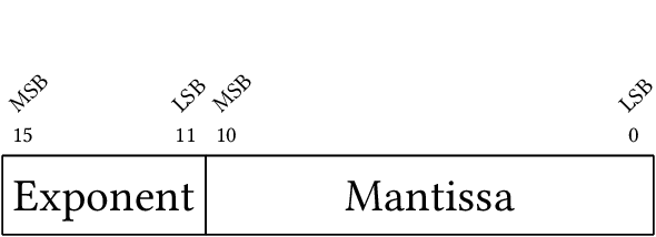
Fig. 6 The PMBus Linear data format
The output voltages use a different, 21-bit format, called LINEAR16 (in contrast to the 16-bit LINEAR11, the names are derived from the mantissa width). This format comprises a 5-bit 2’s complement exponent, reported by the 5 MSBs of the VOUT_MODE command; and a 16-bit unsigned mantissa, reported by READ_VOUT. Many COTS PSUs use LINEAR11 for everything, and this behavior is also possible using a compile-time switch. In the MoniMod, the exponential factor for the LINEAR16 format is fixed to -10, so the voltages reported can be obtained with \(X = Y \cdot 2^-10\), where Y is the 16-bit value returned by READ_VOUT.
Cmd code |
Command name |
Transaction type |
Data len |
Description |
|---|---|---|---|---|
00 + |
Byte write / read |
1 |
set get page |
|
19 + |
Byte read |
1 |
capabilities of the device |
|
1A +* |
Block w / r proc. call |
1 |
query cmd props |
|
20 + |
Byte read |
1 |
read voltage format |
|
3A + |
Byte write / read |
1 |
config fans 1&2 |
|
3B + |
Word write / read |
2 |
set fan 1 speed |
|
3C + |
Word write / read |
2 |
set fan 2 speed |
|
3D + |
Byte write / read |
1 |
config fan 3 |
|
3E + |
Word write / read |
2 |
set fan 3 speed |
|
78 + |
Byte read |
1 |
status byte |
|
7E + |
Byte read |
1 |
status CML |
|
8B + |
Word read |
2 |
read voltage |
|
8C + |
Word read |
2 |
read current |
|
8D + |
Word read |
2 |
read temp. sensor 1 |
|
8E + |
Word read |
2 |
read temp. sensor 2 |
|
8F + |
Word read |
2 |
read temp. sensor 3 |
|
90 + |
Word read |
2 |
read fan 1 speed |
|
91 + |
Word read |
2 |
read fan 2 speed |
|
92 + |
Word read |
2 |
read fan 3 speed |
|
96 + |
Word read |
2 |
read power |
|
99 +* |
Block read |
var |
manufacturer ID |
|
9A +* |
Block read |
var |
model |
|
9B +* |
Block read |
var |
revision |
|
9C +* |
Block read |
var |
location |
|
9D +* |
Block read |
var |
date |
|
9E +* |
Block read |
var |
serial number |
|
AE +* |
Block read |
var |
git commit id |
Commands marked with + or * are:
+ - supported by main fw
* - supported by bootloader
Cmd code |
Command name |
Transaction type |
Data len |
Description |
|---|---|---|---|---|
D1 * |
Word write / read |
2 |
size of the FW to be written |
|
D2 * |
MultiByte write / read |
8 |
FW block to be written |
|
D3 * |
Word write / read |
2 |
checksum of the written FW |
|
D4 * |
Word write |
2 |
calculated checksum of the written FW |
|
D5 +* |
Byte write / read |
1 |
on write turn on btldr pgm mode, reset; on read get which fw is running |
|
D6 +* |
Byte write |
1 |
reset the uC |
|
D7 + |
Block read |
var(1+4) |
get the uptime in seconds |
|
D8 + |
Block write / read |
var(1+4) |
clear / get TMR error count |
|
D9 + |
Byte write / read |
1 |
turn PEC on / off |
|
E0 + |
Block write / read |
var(1+13) |
set / get temp. curve points |
|
E1 + |
Block write / read |
var(1+7) |
set / get temp. matrix points |
|
E2 + |
Byte write / read |
1 |
turn temp. control on / off |
Commands marked with + or * are:
+ - supported by main fw
* - supported by bootloader
Block registers contain in the first byte the size of data that follows. This also applies to the registers with the fixed size like UPTIME_SECS.
Detailed list of PMBus commands
PAGE
The PAGE command is used to select a power rail for the READ_VOUT, READ_IOUT and READ_POUT commands. Allowed values for the page parameter are \(0 \leq N \leq 3\) for the DI/OT Rad-Tol System Board revision and \(0 \leq N \leq 2\) for the fan-tray, RaToPUS and generic prototype revisions.
CAPABILITY
The CAPABILITY command returns one byte of information with some key capabilities of a PMBus device.
Bit(s) |
Meaning |
7 |
Packet Error Checking is supported |
6:0 |
Unused |
Bit 7 of the CAPABILITY register reflects the use of PEC set by the USE_PEC register.
QUERY
The QUERY command takes a command code as an argument and replies with information on the command: whether it is supported, if read or write is supported, and what data format it works with.
VOUT_MODE
The VOUT_MODE command reports the format the device uses for measured voltage related data. The 3 MSBs indicate whether that’s Linear (0b000), VID (0b001) or Direct (0b010), and in the MoniMod’s case it’s always 0b000 for Linear format. The 5 MSBs return either 0x16, for LINEAR16 format used (fully PMBus-compliant operation, fixed \(2^-10\) exponential); or 0x00, for LINEAR11 format used (common for COTS PSUs). See Linear for more details on the specifics of these formats.
FAN_CONFIG_n_m
The FAN_CONFIG_1_2 and FAN_CONFIG_3_4 commands are used to configure the fans at positions 1, 2, and 3. The format of the configuration byte can be seen in Table 12. The two bits that set the tachometer pulses / revolution, which take the values 0–3, correspond to 1–4 pulses per revolution.
Bit(s) |
Value |
Meaning |
7 |
1 |
Fan 1 / 3 installed |
0 |
Fan 1 / 3 not installed |
|
6 |
1 |
Fan 1 / 3 commanded in RPM |
0 |
Fan 1 / 3 commanded in duty cycle |
|
5:4 |
0–3 |
Fan 1 / 3 tachometer pulses / rev |
3 |
1 |
Fan 2 installed |
0 |
Fan 2 not installed |
|
2 |
1 |
Fan 2 commanded in RPM |
0 |
Fan 2 commanded in duty cycle |
|
1:0 |
0–3 |
Fan 2 tachometer pulses / rev |
FAN_COMMAND_n
The FAN_COMMAND_n commands set the desired speed of the attached fans. The value set is either in RPMs (when the fan is configured to be controlled like that) or duty cycle, in the range 0–1000.
STATUS_BYTE
The STATUS_BYTE command returns one byte of information with a summary of the most critical faults.
Bit(s) |
Meaning |
7:2 |
Unused |
1 |
A communications, memory or logic fault has occurred |
0 |
Unused |
The value of STATUS_BYTE is calculated based on other status registers (for now only STATUS_CML). To clear value of STATUS_BYTE, please clear information in other status registers.
STATUS_CML
The STATUS_CML command returns one data byte with contents as follows:
Bit(s) |
Meaning |
7:6 |
Unused |
5 |
Packet Error Check Failed |
4 |
TMR Error |
3:2 |
Unused |
1 |
A communication fault |
0 |
Unused |
Write 1’s in the desired bits positions to clear corresponding errors in the register.
Clearing TMR Error flag sets TMR_ERROR_CNT register to 0.
READ_VOUT
The READ_VOUT command is used to get the measured voltage of the rail indicated by the last PAGE command (by default that would be the first one).
READ_IOUT
The READ_IOUT command is used to get the measured current of the rail indicated by the last PAGE command (by default that would be the first one).
READ_TEMPERATURE_N
The READ_TEMPERATURE_n commands return the measured temperature from the three installed temperature sensors.
READ_FAN_SPEED_N
The READ_FAN_SPEED_n return the fan speed of an installed fan, or 0 in case no fan is installed in the pertinent location.
READ_POUT
The READ_POUT command is used to get the measured power of the rail indicated by the last PAGE command (by default that would be the first one).
MFR_ID
This returns the manufacturer ID string, “CERN (BE/CO)”.
MFR_MODEL
This returns the manufacturer model string, “DI/OT MoniMod”.
MFR_REVISION
This returns the manufacturer revision string.
MFR_LOCATION
This returns the manufacturer ID string, “Geneva”.
MFR_DATE
This returns the manufacturer date string, which currently corresponds to the date of the last release (and not the build used, for example).
MFR_SERIAL
This returns a manufacturer serial string (currently unused, returns “123456789”).
IC_DEVICE_REV
This returns a git commit id of the used firmware.
WRITTEN_FW_SIZE
Before writing a new FW binary through the bootloader, its size in bytes divided by 8 has to be given using this command. The written value can be read.
WRITTEN_FW_BLOCK
A new binary is written to the bootloader in consecutive chunks of 8 bytes, using this command. The written data can be read.
WRITTEN_FW_CHKSUM
After setting the size of the FW binary with WRITTEN_FW_SIZE and
writing it with the WRITTEN_FW_BLOCK command, its SYS-V checksum
should be written with this command. This command also resets the
write pointers.
The written checksum can be read. Please note that this is not
the calculated checksum. The calculated checksum is stored in
LOCAL_FW_CHKSUM (LOCAL_FW_CHKSUM).
LOCAL_FW_CHKSUM
After writing the new firmware, this command can be used to get the checksum calculated by the MoniMod. Please note that it is up to the writer to verify (compare) the checksum.
BOOT_NEW_FW
The BOOT_NEW_FW command changes the execution mode of the Firmware. When the byte 0xAD is written to this register the running firmware is switched between bootloader and main mode. When the proper byte is received, a special code is written to or removed form the flash memory to let the bootloader to stay in bootloader mode or proceed to the main firmware. More information is available in the section Bootloader.
The read gives the information which firmware is actually running.
Value
Meaning
1
Bootloader
2
Main firmware
UC_RESET
Writing 0x5A byte to this register triggers a uC reset. Other writes are silently ignored.
UPTIME_SECS
Get the uptime of the MoniMod (in seconds).
The fist byte of the register contains the number of bytes of data. For this register, its value is fixed to 4.
TMR_ERROR_CNT
When software mitigation through COAST is enabled (see TMR using COAST), one can access the TMR_ERROR_CNT counter using this command. Setting TMR Error bit in STATUS_CML clears the value of this register.
It is possible to clear the TMR Error counter by writing 0’s as data to this register.
The fist byte of the register contains the number of bytes of data. For this register, its value is fixed to 4.
USE_PEC
The SMBus specification indicates that a device’s PEC support could be enabled or disabled at will.
The read gives the information whether the PEC is enabled.
Value
Meaning
0x00
PEC disabled
0x01
PEC enabled
To change the state of the PEC, the proper magic value has to be written to this register. All other values are silently ignored.
Value
Meaning
0x0F
Disable PEC
0x37
Enable PEC
The command itself is used without a PEC byte appended, no matter whether the function is enabled or not.
TEMP_CURVE_POINTS
As described in the Temperature control section, the temperature curve can be set separately for each fan. To do this, the format in Fig. 7 has to be used.
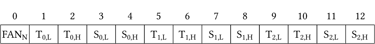
Fig. 7 Temperature curve data frame
The first byte specifies the fan number (0-2), following bytes contains data specific for temperature curve.
The first read after the write to this register allows to get just stored data for the particular fan. The following reads of this register iterates over all fans and allow to get their data.
The fist byte of the register contains the number of bytes of data. For this register, its value is fixed to 13.
TEMP_MATRIX_ROW
As described in the Temperature control section, the temperature matrix can be set separately for each fan. The data format for the operation is illustrated in Fig. 8.
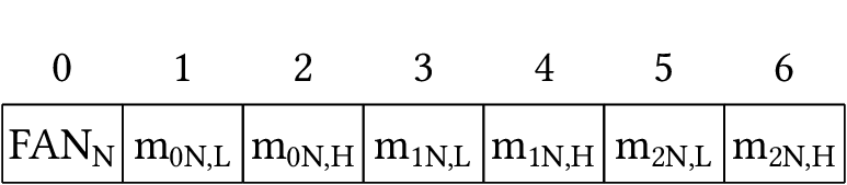
Fig. 8 Temperature matrix data frame
The first byte specifies the fan number (0-2), following bytes contains data specific for temperature control.
The first read after the write to this register allows to get just stored data for the particular fan. The following reads of this register iterates over all fans and allow to get their data.
The fist byte of the register contains the number of bytes of data. For this register, its value is fixed to 7.
TC_ONOFF
Using the TC_ONOFF command with a zero argument disables Temperature Control, while any non-zero value enables it.
Fan control PID
When the fans connected provide a tachometer output, fan speed control can be enabled. This is implemented using PID controllers, with each fan having its own instance. The main data structure of the PID implementation is
-
struct
pid_cntrl_t
This is used by the main software to set the PID setpoint, and by the PID controller to hold integration data. The main function that has to be called every timestep is described below:
-
float
pid_compute(pid_cntrl_t *pid_inst, float input)¶ use this function with a PID structure and an input to calculate the output for each timestep.
Compute the PID output for the next timestep
- Return
the PID controller output
- Parameters
pid_inst: struct that holds the PID controller’s configurationinput: the current input to the PID controller
Temperature control
The MoniMod implements a very flexible temperature control scheme. Each fan can be assigned its own 3-point temperature–speed curve, as in Fig. 9. Temperatures outside the set range will adopt the speed of the minimum and maximum temperature, accordingly.
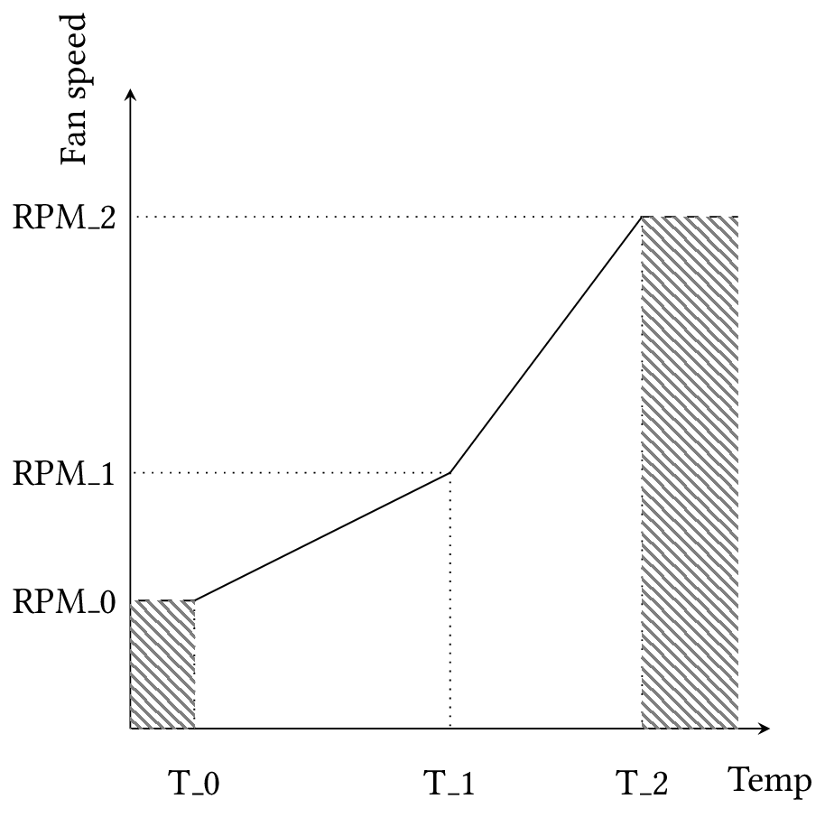
Fig. 9 Temperature curve
Moreover, the temperature each fan considers for its curve is a weighted product of all three monitored temperatures, as in Fig. 10. This allows one to easily configure the MoniMod to match a wide variety of fan / sensor setups, e.g.:
each fan is assigned its own temperature sensor
all three temperatures are averaged to give a more precise system temperature
one fan blows directly on a sensitive component which is monitored, the other two fans handle the rest of the system

Fig. 10 Temperature mixing matrix
Test firmware
To help with development, a test firmware has been written for a Feather M0 Basic minimal development board.
Mitigation measures
The MoniMod will be used in radiation environments. Although its function is not critical and it can be remotely reset upon loss of communication, some measures have been taken to minimize interruptions and data corruption, leading to an improved QoS.
TMR using COAST
The COAST LLVM passes can be optionally used to automatically implement TMR (Triple Modular Redundancy) in important and long-lived variables. This can particularly benefit the integrity of dynamic configuration data that gets set in the memory once and then gets read periodically, or state machines such as the one in the I2C interrupt handlers which is critical for stable communications.
NOPs and trampolines
The Program Counter is also sensitive to SEUs; in fact, execution can
sometimes jump to an invalid address. To help mitigate failures owed
to this mechanism, any region of unused memory space has been filled
with NOP instructions, and a small trampoline function as an
epilogue that will reset the stack pointer and jump to the device
initialization code. Furthermore, the instruction that comprises the
main loop has been placed at a “strategic” location, aligned by
0x8000: that way, a bit-flip in any of the lower bits will
send execution to the upper memory region, filled with the NOPs and
concluding at the trampoline.
Watchdog
The uC integrates a watchdog peripheral: this is fed every time the main timer callback runs, i.e. every 10ms. The watchdog is set to trigger if it doesn’t get fed for 20ms – as soon as the main loop skips a beat. That ensures a quick revival of the uC and should lead to minimal downtime.
Bling scrubbing
Blindly scrubbing the configuration of peripherals can be used to reduce gradual corruption of their configuration during operation. The frequency has to be carefully selected to minimize downtime.
Note
This hasn’t been implemented yet, this is a reminder to do it.
Stack protection
The compilers’ stack protection feature is enabled to catch the corner case that some loop goes awry and corrupts the stack due to some SEU. In case that happens, the uC quickly gets reset.
Toolchains
The project can be built with GCC and Clang / LLVM compilers; one can switch between the two simply by setting a Makefile variable. Note, however, that TMR only works with Clang.